1. Snap joint, AKA snap fit joint, is a common structure for connecting and fixing plastic injection molding products. It is able to replace the fixing screws when the strength requirement is not high.
The design point of the snap joint lies in “joint”, i.e., it has to ensure secure connection, meet the test strength and fulfill the installation purpose. The snap joint is often applied to fixation of decorative parts, assembly of face / back casings, fixation of screens, stopper of buttons, engagement of covers and many other structures.
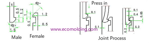
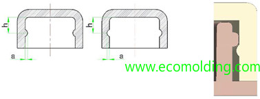
2. Snap-fit Joint is composed of the pin and the box; the pin is convex and the box is concave.
How does the snap fit joint work:
Before Engagement: There is a guiding bevel to guide the direction of the engagement, both the pin and the box are designed with the lead-in angle, usually 60° and 45°.
During Engagement: the elastic arm of the pin is deformed and pressed in. The elastic arm should be able to deform, with sufficient strength. Generally, the amount of deformation≥ the amount required for engagement.
After Engagement: the pin and the box are connected, and are not easy to separate. It is required that the engagement surface or angle is smaller than the guiding bevel.
3 Common types and sizes of snap fit joint
- For fixation of decorative parts, usually one end is inserted into the other for connection. The amount of engagement is 0.3-0.7mm, and the insertion is 0.6-1.5mm, such as decorative pieces, battery covers, screen fixing and assembly of face/back casings, etc. There is also a full snap-in structure, with more snap joints and supplemented with auxiliary guiding ribs, such as mobile phone cover, but we will not introduce it here.
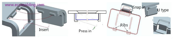
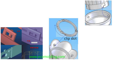
- The following figure shows a commonly seen concealed internal snap joint, which is not easy to disassemble, i.e., the structure cannot be disengaged; but, the insertion structure on the pin can be easily disassembled by inserting through the perforation. For example, the pin structure of the router is designed on the inner side of the face casing and the box inside the back casing, so it is difficult to disengage them. The LCD screen casing also employs the similar snap joint structure.
- The following figure shows the common assembly of the front and back casings. In the first set of drawings, a rib is usually added to the pin for staggering. There are no special requirements for the 2nd set of drawings. The box combines with the pin rabbet, and the pin with the box rabbet. With regard to the combination of the box with box rabbet, and the pin with pin rabbet, corresponding modifications can be made according to the structures shown in the following two sets of drawings, of which the assembly is similar.
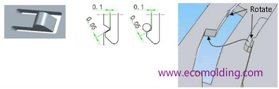
- The forcible disengagement of the snap joint is determined by the material and toughness. The softer the material, the more possible for forcible disengagement. Generally, the forcible disengagement on a single side is ABS: 0.3mm, PC: 0.5, PP: 0.8, TPE: 1.5, etc. Forcible disengagement is related to the thickness and toughness of the wall. The depth of forcible disengagement can be increased slightly if the material is tough enough. The actual structure is determined by specific conditions.
- Manual snap joint is usually applied to the sliding structure, such as battery cover, rotating ring and other structures. One end is a snap button, and the other a tooth or a cylinder. The other form does not involve a snap button, but with forcible engagement / disengagement, of which the amount of engagement is usually between 0.3 and 0.8.
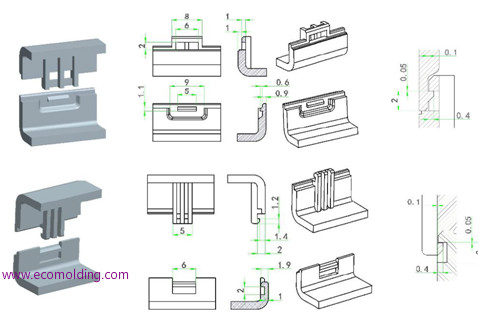
- Other commonly seen snap joints:
4 Considerations for the design of snap joints
Snap joint design needs to consider the layout, quantity, location, installation form and strength. Tips:
a. For regular shapes, layout should follow the circular and square snap joint distribution shown in the figure on the right; when the width of the square shell ≤ 20, no snap joint is needed; 20 < shell width ≤ 50, 1 to 2 snap joints; for circular shells, the snap joints are usually evenly distributed. For fool proofing, you can move the snap joint slightly to ensure even distribution of snap joints.
b. For irregular shapes, select the installation form according to the assembly direction. The curve edge is prone to warpage and disengagement under force, so the snap joint + rib structure is often used;
c. The snap joint should be as close as possible to the corner to prevent warping, and assembled in conjunction with screws; the quantity of snap joints should be minimized on condition that strength is guaranteed.
d. The installation form of snap joints, and the positive and negative buckles should allow for easy assembly / disassembly, while taking mold production into consideration;
e. Prevent shrinkage and weld marks around the snap joint;
f. The space for snap joint lifter movement is not less than 5, generally selecting 8. There should be no interference during return, so a flat plane is preferred;
g. Design an R angle on the non-installation side of the snap joint, which should not interfere with the snap-in process.
h. Guiding elements of snap joint, features: rabbet and rib, etc., which are described above. S