The ejection of a plastic product is the last step in the plastic injection molding process. The quality of the ejection determines the quality of the plastic product. When the mold opens, the plastic product must be retained on the mold half (usually the core) with the ejector mechanism that is used to release the plastic product.
I. Ejector Pin Design Principles:
(1) In order to prevent the plastic product from deformation during ejection, the ejection force has to be distributed as evenly as possible, and as close as possible to the core wrapped by the shrinking plastic or to the part that is difficult to eject, e.g., the elongated pillar of a plastic product is ejected with an ejector sleeve.
(2) The ejection force should be applied to the part with the strongest rigidity and strength of a plastic product (avoiding action on the thin section), and the active surface should also be as large as possible, such as the outstanding flange, the rib and the wall edge of the shell, etc. Most barrel-shaped products are released by using the ejector plates.
(3) To avoid ejector marks affecting the appearance of the plastic product, the ejection position should be set on the concealed surface (internal) or non-appearance surface of a plastic product; for transparent plastic products, the selection of the ejection position and the ejection form should be taken special care of.
(4) To avoid ejector marks and deformation of a plastic product caused by vacuum adsorption, the combined ejection approach or ventilation with porous steel may be applied. For example, ejector pin combined with ejector plate, or ejector pin combined with ejector block. The clearance of ejector pin should be appropriately enlarged for ventilation, and use an intake valve when necessary.
(5) The ejector mechanism should be reliable and flexible, with sufficient strength and wear resistance. For example, with regard to ejections with swing rod and wedge, the strength and wear resistance of the sliding surface should be improved, with lubricating grooves designed on the sliding surface; Nitriding treatment may be applied to improve surface hardness and resistance to wear.
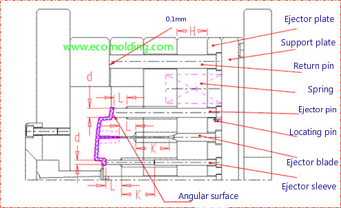
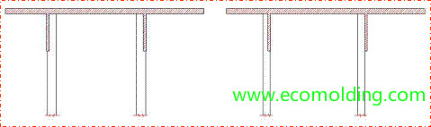
(6) The length of the mold return pin should ensure contact with the cavity or a distance of less than 0.1 mm after the mold closes, as shown in the figure above.
(7) A return spring is usually used for the return of the ejector plate; since the return spring is not reliable, it cannot be used as the reliable early return mechanism.
II. The Commonly Used Ejector Mechanism
1. Ejector Pin / Ejector blades
1.1 The commonly used methods for ejection of plastic products include ejector pin, ejector sleeve, ejector blade and stripper plate. Since ejector sleeve and ejector blade are higher in price (8 to 9 times more expensive than ejector pin) and stripper plate is used for the ejection of thin barrel-shaped plastic products, the most commonly used is the ejector pin. When it is not possible to design an ejector pin around a plastic product, e.g., mainly with deep ribs in the surrounding area, i.e., rib depth is 15mm, the ejector blade can be used for ejection. The surface hardness of ejector pin and flat ejector pin is above HRC55 and the surface roughness is less than Ra1.6. For the ejector pin and the flat ejector pin mechanisms, please refer to the figure.
The design points are stated as below:
(1) When the ejector pin diameter is no larger than Ø2.5mm, the shoulder ejector pin is selected to improve the strength of the ejector pin.
(2) Ejector blade, shoulder ejector pin K/H.
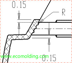
(3) When the ejection surface is a slope, the fixed end of the ejector pin must be provided with a locating pin; to prevent the ejector from slipping, the slope can be designed with multiple R slots, as shown in the figure.
(4) For the ejector blade, the matching distance between the pin and the hole is L = 10-15mm; for small diameter ejector pins, L is 5 to 6 times of the diameter.
(5) The ejector pin is at least 0.15mm away from the edge of the cavity.
(6) Avoid meeting between the ejector pin and the cavity, which might probably cause damage to the core, or flashing.
1.2 The Placement Principles of the Ejector Pin
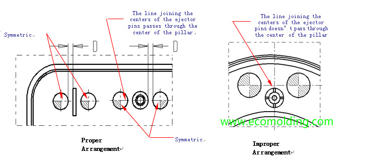
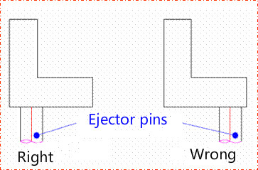
(1) The ejector pin should be arranged in the way that the ejection force is as balanced as possible. The mold release force required for complicated structures is larger, so the number of ejector pins should be increased accordingly. (2) The ejector pin should be placed in effective parts, such as ribs, pillars, steps, metal inserts, thick parts and other structurally complex locations. The ejector pin on both sides of the rib and the pillar should be arranged as symmetrically as possible. The distance between the ejector pin and the ribs and pillars is usually D=1.5mm, as shown in the following figure. In addition, it should be ensured that the line joining the centers of the ejector pins on both sides of a pillar passes through the center of the pillar.
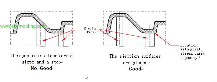
(3) Avoid designing ejector pins across steps or on a slope. The ejection surface of the ejector pin should be as flat as possible. The ejector pins should be placed at structural locations where the plastic product possesses great stress carrying capacity, as the figure shows.
(4) The ejector blades should be used at locations with deep ribs (depth ≥ 20 mm) or when it is difficult to arrange a ejector pin. When the ejector blade is required, the ejector blade should be in the form of an insert to facilitate processing. As shown in the left figure below:
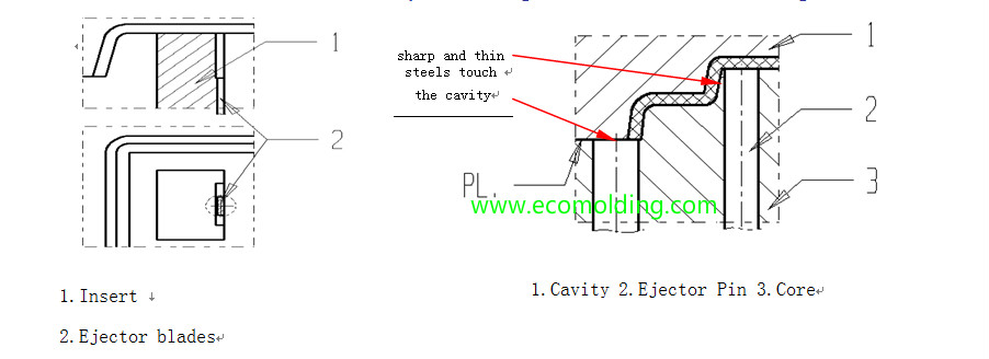
(5) Avoid pointed and thin steels, especially the ejection surface of the ejector pin cannot touch the cavity. As shown in the right figure above:
(6) The ejector pin arrangement should consider the spacing between the ejector pin and the cooling channel, so as to avoid affecting the processing of the cooling channel or causing leakage.
(7) Consider the venting function of the ejector pin. For venting purposes during ejection, the ejector pin should be placed in the part where it is easy to form vacuum. For example, on a large plane in the cavity, although the wrapping force of the plastic product is relatively small, it is easy to form a vacuum, which leads to an increase in mold releasing force.
(8) For plastic products with requirements for surface finish, the ejector pin cannot be placed on the exterior surface, but other ejection methods should be applied.
(9) For transparent plastic products, the ejector pin cannot be placed in the area where light transmission is required. Selection of product ejection locations
(10) The ejection location should be where the ejection force is large, such as the locations near the core and the rib.
(11) The ejection location should be where the strength and rigidity are the largest, as shown in the figure:
(11) In the parts of poor ventilation, consider adding ejector pins to facilitate ventilation, e.g., under a cross rib.
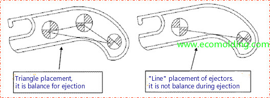
(12) The ejector pin placement should be arranged in a triangle for balanced ejection, as shown in the figure:
1.3. Principles for Selection of Ejector Pins
(1) Select larger diameter ejector pins. That is, in the case of a big enough ejection area, a larger diameter and larger size ejector pin should be used.
(2) The specs of the ejector pin should be as little as possible. When using an ejector pin, the size of the pin should be adjusted to minimize its specs, and try to select the preferred size series. See Section 11.1 of Chapter 10 for dimensional specs.
(3) The selected ejector pin should meet the requirements for ejection strength. When ejecting, the ejector pin should withstand a large pressure. In order to avoid deformation of small ejector pins, when the diameter of the ejector pin is smaller than 2.5mm, the shoulder ejector pin should be used.
(4) The ejector pin diameter is preferred to be an integer. Don’t make it a decimal or non-standard, e.g., Ø 3, 4, 5, 6 and 8.
1.4 The Matching Clearance of Ejector Pin and Ejector blade
The matching locations for the ejector pin, the shoulder ejector pin and the flat ejector pin are shown in the figure, and the requirements are as follows:
(1) The ejector pin head diameter d and matching size of the ejector blade with the core t and w should be set according to the clearance of 0.04mm.
(2) The size of the ejector pin and ejector blade holes in the non-matching sections are d = 0.8 mm or d1 = 0.8 mm, and the clearance between the fixed end of the step and the ejector retainer plate hole is 0.5 mm.
(3) The bottom end of the ejector pin and the ejector blade must be flush with the bottom of the ejector retainer plate.
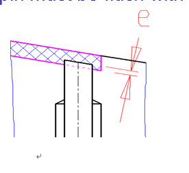
(4) As shown in Figure 6.1.7, the top surface of the ejector pin and the core surface should be flush, or higher than the core surface by no higher than 0.1mm (e£0.1mm).
1.5 Fixation of Ejector Pins
(1) The ejector pin is usually fixed on the machining table of the ejector retainer plate. In order to prevent the ejector pin from rotating, 2 ways are usually applied: i. locating pins axially near the step of the ejector; and ii. locating pins horizontally.
(2) Fixed by the headless screw. As shown in the figure, this method is used when there is no pad at the end of the ejector pin, usually applied to the fixation of the ejector sleeve pin and the ball-shaped sprue puller of a three-plate mold.
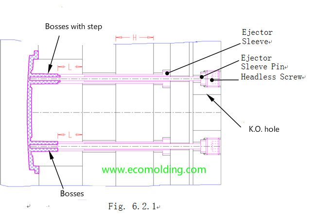
2 Ejector Sleeve
The ejector sleeve, often applied to guide pins of 20mm long, is as shown in the figure. The standard ejector sleeve has a surface hardness of HRC 60 and a surface roughness of Ra1.6. In addition, the wall thickness of the ejector sleeve should be 1mm; when arranging the ejector sleeve, the ejector sleeve pin cannot interfere with the ejector.
2.1 Matching Requirements of the Ejector Sleeve
The mold release matching relationship of the ejector sleeve is shown in Figure as below and the matching requirements are as follows:
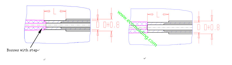
(1) The matching length of the ejector sleeve with the core is L = 10-15mm, and the matching clearance of the diameter D is £0.04mm.
(2) The non-matching section is D = 0.8mm.
2.2 Fixation of Ejector Sleeve Pin
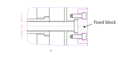
The ejector sleeve is fixed to the base plate,
usually with a headless screw as shown in the figure.
When the diameter of the ejector sleeve is d = 8mm or 5/16,
the fixed end is fixed by a spacer block, as shown in the figure.
2.3 Conditions for Selection of the Ejector Sleeve
(1) When the bosses height is ≥ 20mm; however, when there are strict requirements for the height of bosses, it is not allowed to use the ejector sleeve.
(2) When it is difficult to arrange the ejector pin, because the structure of the guide pin is complicated;
(3) Transparent parts, which don’t allow ejector marks on any locations except bosses;
(4) In general circumstances, the wall thickness of the ejector sleeve must be ≥1.0mm;
(5) The length of the ordered ejector sleeve = the actual required length + 5.0-10.0mm, and is rounded to the preferred size ending with 5 or 0.
3.Stripper plate
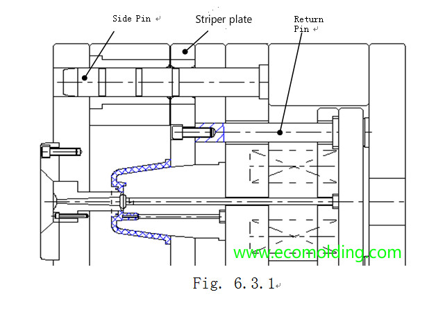
3 Stripper Plate
The stripper plate is shown in
Figure 6.3.1. This mechanism is suitable for
plastic cylindrical / thick-walled products, and
those that do not allow ejector pin marks, or a
small-sized multi-chamber case (such as a
plastic button product). It possesses the advantages of uniform ejection force, stable ejection and resistant to deformation. It is not suitable for plastic products with complicated shapes around the parting surface, or plastic product that makes it hard to machine stripper plate holes.
3.1 Key Points of the Mechanism
Key Points of the Ejector Plate Mechanism:
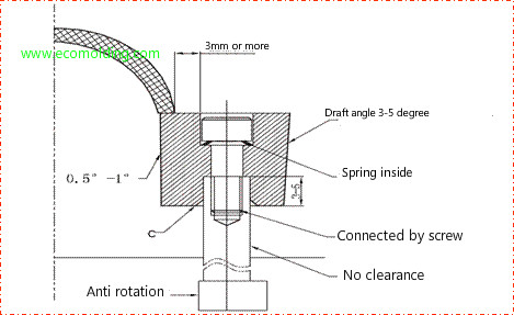
(1) The matching structure of the stripper plate and the core should be tapered; this is able to reduce motion scratch and facilitate guidance; the tapered slope should be 3-108, as shown in the figure.
(2) The inner hole of the stripper plate should be 0.2 to 0.3mm larger than the molding section of the core (single side), as shown in the figure.
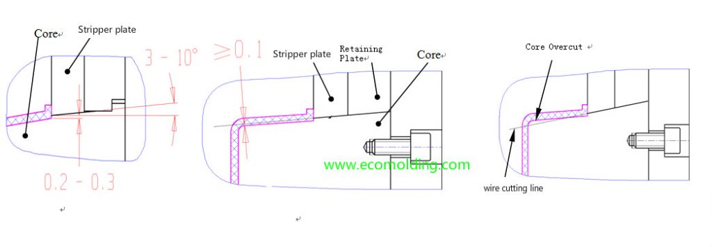
(3) When the core taper is cut by wire, pay attention to the clearance of 0.1mm between the wire cut and the top of the core, as shown in the figure; avoid overcutting of the core during the wire cutting process, as shown in the figure.
(4) The stripper plate is connected to the return pin by a screw.
(5) When ordering the mold base, pay attention that the stripper plate and the guide pin matching hole must be installed with a straight guide (straight sleeve), and the selection of the stripper plate material should be equivalent to M202.
(6) After ejection with the stripper plate, it must be ensured that the plastic product is not retained on the stripper plate.
4 Ejector Block
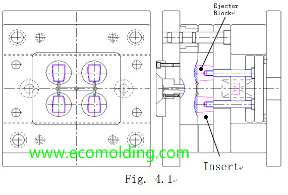
For plastic products that don’t allow
any ejector marks (such as transparent
plastic products), but have high
requirements for surface finish, the
ejector block can be applied by leveraging the whole surface of the plastic product, as shown in Figure 8.4.1.
Key Points of the Ejector Block:
(1) The ejector block should have a higher hardness and a lower surface roughness; the material should have a certain hardness difference with the insert (usually over HRC 5); the ejector block should be nitrided (except that stainless steel should not be nitrided);
(2) There should not be flashing in the clearance
of the ejector block with requirements for smooth
sliding, and the sliding surface of the ejector block should
be designed with a lubricating groove.
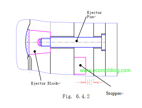
(3) The matching surface between the ejector block and the insert should be tapered, and it is not allowed to use a straight surface.
(4) The tapered structure of the ejector block should meet the requirements shown in Figure 6.4.2; the ejector stroke (H1) is greater than the ejection height of the plastic product, and at the same time less than half of the height of the ejector block.
(5) The ejector block should ensure stable mold release, and more than two ejector pins must be used for large ejector blocks.
Ejector block can be applied to some thin products that are not possible for application of ejector pins, as well as to the high products with a large wrapping force.
Ejector Pin for Ribs
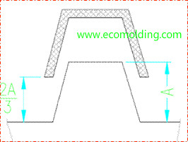
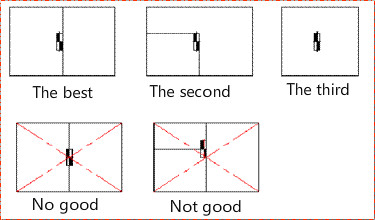
The ejector pin should be at least 1mm from the top of the core, but no more than 2.5mm. Be careful not to let the ejector pin damaging the product.
Try to place the ejector pin at the bottom of the product, e.g., for Pin A, try to keep it 0.3mm away from the core. Avoid placing it on the top, like Pin B.
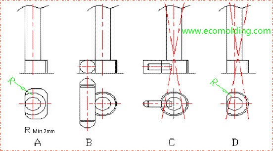
If an ejector pin has to be placed on a slope, the location A is preferred, and select location B if that is not possible, followed by location C, because the product tends to move on the slope, and the ejection force is reduced due to the slope.
If the ejector pin has to be placed on location C, anti-slip measures must be taken for the pins, so as to increase the ejection force.
Determination of the Ejector Stroke:
a. Usually choose for the whole product to be ejected: S (ejector stroke) = product height (H) + margin (15-20) mm
b. In special circumstances, partial ejection might be considered. See figure 3:
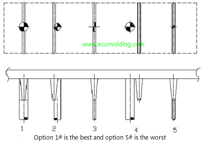
Size of Ejector Pin Clearance:
If the cavity is shaped, the ejector pin should be fixed. Note: Priority is given to fixing both sides, to prevent the ejector pin from moving.
Plan A should be first considered in the design process. Plan C may be considered during mold modification.
Use a mold plate for localization as preferred.
Design of the ejector blade location
When designing the flat ejector pin, consider whether the angle lifter and the straight ejector bar will be caught by the product, leading to product release failure.
Delayed Ejection
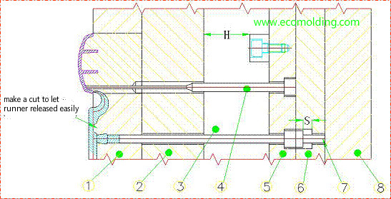
In some molds, the action of some ejector pins needs to be delayed to achieve a better ejection effect. As shown in the figure below, since the submarine gate is close to the plastic product, if synchronous ejection is applied, the submarine gate may be damaged during ejection. Therefore, ejector pin 3 adopts the delayed ejection. In the early stage of the ejection, ejector pin 3 stays still. When the ejector stroke reaches S, ejector plate 6 first pushes ejector pin 7, and then pushes ejector pin 3 out of the runner, so as to prevent the gate from damaging the plastic product. In the figure, H is the complete ejector stroke, and the ejector stroke of ejector pin 3 is H – S, wherein the value of S depends on the shape of the submarine gate and its proximity to the plastic product.
Please feel freely to contact us if you are looking for professional plastic injection molding manufacturer.