Purpose of the Guiding system: Positioning & Guiding
Maintain the correct clamping of the core and the cavity, as well as the correct shape of the cavity after clamping.
Guide the mold core to be clamped in sequence, to prevent the core from being damaged during the mold closing process. Able to withstand certain lateral forces.
Guiding system via Guide Pin
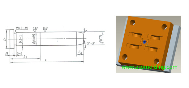
Guiding via the guide pin refers to that the clearance between the guide pin and the guide bush allows the latter to slide over the former. The clearance is generally H7/h6, and the main components are the guide pin and the guide bush.
Guide Pin
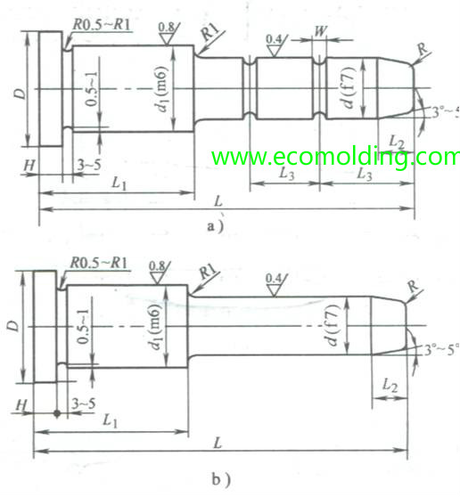
1) Headed Pass-through Guide Pin
In small batch production, the headed guide pin usually does not require the guide bush, but engages directly with the guide hole in the mold plate; in most cases, it needs to be matched with the guide bush. The headed guide pin is usually applied to simple molds
2)Shoulder Guide Pin
The shoulder guide pin is applicable to molds with high precision requirements and large production batches. It is usually applied in conjunction with the guide bush to maintain guiding accuracy after wear by replacing the guide bush.
Design Points of the Guide Pin
1)The small-sized molds adopt the headed pass-through guide pin, while the large-sized molds adopt the shoulder guide pin.
2)The guide pin must have sufficient flexural strength, with a wear-resistant surface and a flexible core. Therefore, it usually adopts the carburized and quenched low carbon steel (20 Steel), or quenched carbon tool steel.
3) The end of a guide pin is often designed to be tapered or hemispherical for easy entry into the guide sleeve.
Guide bush
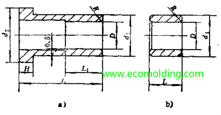
The standard guide sleeve commonly used in plastic injection molds includes two categories: the straight guide bush and the headed guide bush.
1) Straight Guide Bush
The straight guide bush is simple in structure, easy to manufacture, and is applicable to small and simple molds.
2) Headed Guide bush
The headed guide bush is complex in structure, difficult to manufacture, and is mainly used for large molds with high precision requirements.
Design Principles of the Guide Bush:
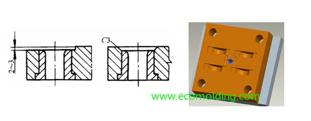
①In order for the guide pin to enter the guide bush smoothly, there should be a chamfer on the front end of guide bush.②The guide hole should be designed into a through hole. If it is not machined into a through hole, the air in the hole cannot escape, which will impose a back pressure on the entry of the guide pin; and also, it is not easy to clean the scrap falling into the hole, which hinders the entry of the guide pin. If the mold plate is thick and a through hole is not possible, a through hole should be added to the side wall of the blind hole, or venting slot should be designed on the side wall of the guide pin and the open end of the guide hole. ③Guide Sleeve is usually made of hardened steel or copper and other wear-resistant materials, but its hardness should be lower than that of guide pin, so as to improve friction and prevent burrs on the guide pin or the guide bush.
Configuration and Fixing Method of the Guide Pin and the Guide Bush
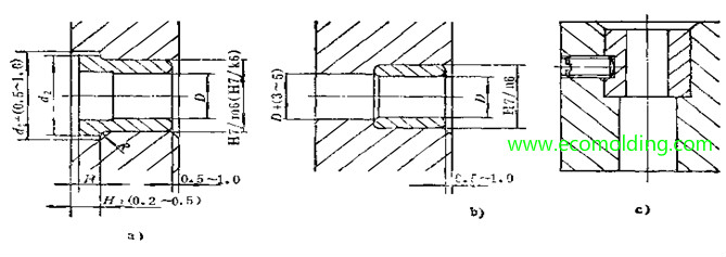
1)The guide pin and the guide bush usually slide relatively, and the matching clearance generally is H7/h7 or H8/h8. The positioning between the guide pin, the guide bush and the mold plate usually adopts H7/k6 or H7/m6 as transition. The matching length between the guide pin and the guide bush is usually 1.5 to 2 times of the diameter, and the rest is reamed (for about 0.5 to 1 mm).
2)The guide pin and the guide bush are generally fixed by steps. The straight guide bush without steps can be fastened with a stop screw.
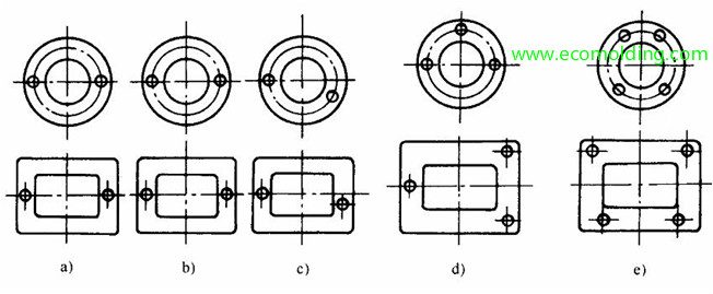
Size, Quantity and Arrangement of the Guide Pin and the Guide Bush
(1) Size of the Guide Pin and the Guide Bush
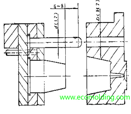
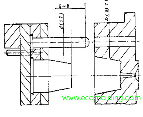
①The diameter of the guide pin is determined by the exterior dimensions of the mold and can be selected with reference to the standard mold base data. ②The length of the guide pin should normally be 6-8mm higher than that of the core, so as to prevent the core from entering the cavity and colliding with it when the guide pin is not properly guided. ③The diameter of the guide pin for the ejection system is equivalent to the size of the return pin.
(2) Quantity and Arrangement of the Guide Pin and the Guide bush
Try to select a standard mold base. If not, you should pay attention to the following points for their guiding system: ①The number of the guide pins and the guide bushes between the mold core and the mold cavity generally ranges from 2 to 4. In general, the guide pins should be reasonably arranged around the parting surface. ②Small molds, be it round or rectangular, usually adopt only two guide pins. ③In order to simplify processing, the large and medium-sized molds may adopt 3 or 4 same-diameter guide pins that are asymmetrically arranged.