Sources of air in the Mold
Air trapped in the cavity and the gating system; the moisture contained in the plastic material is evaporated into gas under the injection temperature; the gas generated by plastic decomposition; the gas generated by the volatilization or chemical reaction of certain additives contained in the plastic; the gas generated by the volatilization of release agents.
Poor Venting Leads to Defects
1). Hinder the normal and fast filling of the molten plastic;
2). The heat generated through air compression may burn the plastic;
3). The gas may intrude into the plastic part and thus lead to such defects as pores and looseness under the conditions of fast filling, high temperature, low material viscosity, excessive injection pressure and part thickness.
Design of Mold Venting System
1. Mold Venting Design Points
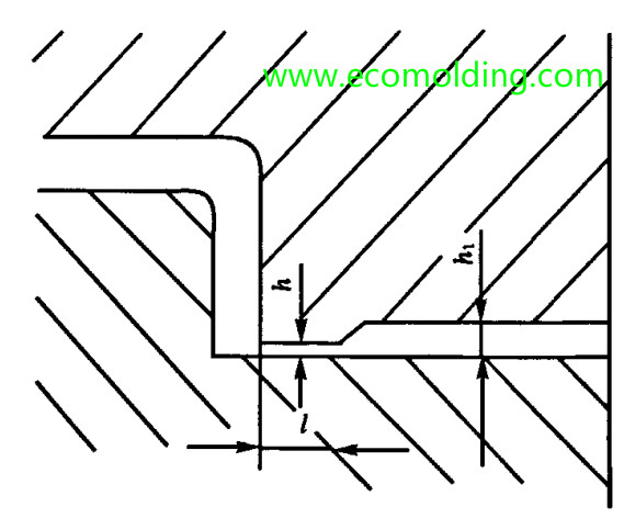
The mold vent should be designed on the cavity side of the parting surface, in order to facilitate mold manufacturing and cleaning. Try to set it at the end of the material flow and the thicker section of the plastic part. The venting direction should not face the operator, but should be machined into a curve or bend, to prevent the operator from being burnt during gas injection. The vent usually measures 1.5 to 6 mm in width, and 0.02 to 0.05mm in depth. It is preferred that the plastic material does not enter the vent.
2. Mold Venting Methods
(1). Air Vents
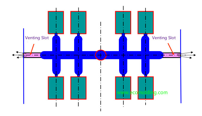
The mold vent is usually located on the cavity, around the cavity or at the far end of the melt flow. Figure 6-2: A circular air vent on the insert parting surface
★ Venting via Parting Surface
Air vents in the mold runner
(2). Vacuum Pumping
This method requires the parting surface of the mold to be well matched, and the gas in the cavity is evacuated through pores. However, a vacuuming device is required, which increases the cost of the mold, so usually it is not adopted.
(3). Venting via Clearance
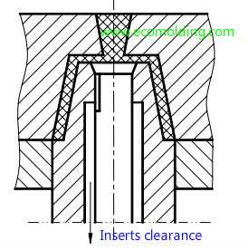
1). The clearance between matching surfaces of the inserted part, such as the cavity and core inserts.
2). The clearance of side core-pulling parts;
3). The clearance between ejector parts (ejector pin, ejector pad);
4). The clearance on the parting surface (average roughness);
When using the clearance for venting purposes, the clearance might get blocked after long period of use, so it should be cleaned regularly to keep it unobstructed.
(4). Venting via Porous Metal
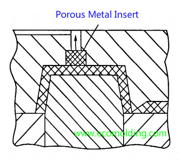
In recent years, a new material featuring a uniform interconnected interior pore structure, the porous metal – has been developed, which gives an outstanding venting performance when it comes to mold cavity ventilation. When it is not easy to vent a certain part of the cavity, the porous metal may be selected as the material of the cavity insert, to achieve effective venting.
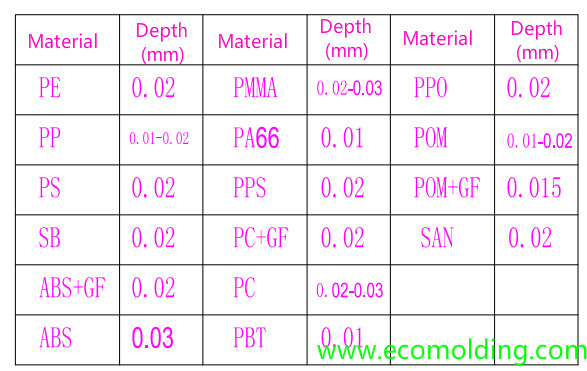
Plastic overflow value and Max. Mold Venting depth
The venting depth should be able to guarantee smooth air venting, while keeping the molten plastic inside at the same time.
The venting depth for the plastic material falls into three ranges:
◆ Max.Venting depth for low viscosity material: 0.01-0.03mm
◆ Max.Venting depth for medium viscosity material: 0.03-0.05mm
◆ Max.Venting depth for high viscosity material: 0.05-0.08mm
Please feel freely to contact us if you are looking for a professional plastic molding company.