Mold Spring Specs
The rectangular-sectioned mold spring (mold spring for short) is mainly applied to stamping dies, metal die casting molds, plastic injection molds, and structurally sophisticated mechanical equipment. Mold spring is mainly made of 50CrVA, which features a small installation volume, outstanding elasticity, strong rigidity, high precision, a rectangular material shape, surface color separation coating (plating), and an aesthetic appearance. Currently, the standard products our company produces mainly refer to the Japanese B5012 Standard (extra light load; light load; medium load; heavy load; extra heavy load), American Associated Spring Standard (medium duty, medium heavy duty, heavy duty, and extra heavy duty), American ISO Standard (light load; medium load; heavy load; extra heavy load), and German ISO10243 Standard (1S, 2S, 3S, 4S, 5S), offering thousands of specs for the user to choose from.
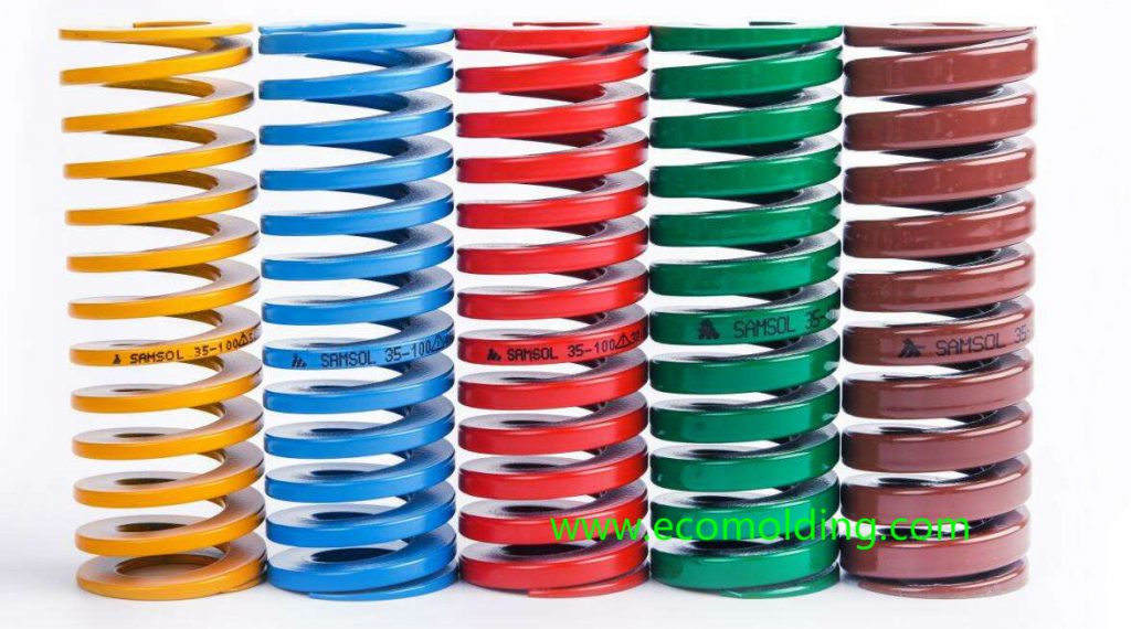
Based on the loading capacity, mold springs mainly fall in the categories of
Extra light load (yellow), light load ( blue), medium load ( red), heavy load (green) and extra heavy load ( brown).
Design of Return Pin Spring:
1.Spring Design Principles
Spring Compression – Preload ≥ Ejector Stroke;
i.e., 30%-40% free length of spring - 8%-10% free length of spring ≥ Ejector Stroke
Free length of return spring = Ejector Stroke ÷ (30%~40% - 8%~10%)
Load (Load/spring x number of springs) ≥ 1.5 of Weight of Ejector Plate;
2. Calculation of Spring Load:
Load/spring = Constant (kgf/mm) x L (Compression)
3. Calculation of Ejector Plate Load:
Ejector Plate (Upper & Lower Plates) Load = Volume (L*W*H) x Density (7.8/1000)
4. Common Spring Types:
The return spring usually adopts the SUP material (flat spring), of which the commonly used types include:
DF Extra light load spring (Yellow)
DL Light load spring (Blue)
Note: Please indicate type (DF & DL) and color during selection;
5. Relationship between the life cycle and compression ratio of commonly used springs
| Type | 300000 | 500000 | 1000000 |
| Extra Light Load (DF) | 0.5 | 0.45 | 0.4 |
| Light Load (DL) | 0.4 | 0.36 | 0.32 |
6. Experience-based method to determine the number and diameter of return spring:
See the table below.
| Length of Mold Base | ≦200 | 200﹤L≦300 | 300﹤L≦400 | 400﹤L≦500 | 500﹤L |
| No. of Springs | 2 | 4 | 4 | 4 | 4 |
| Spring Diameter | 1” | 1” | 1—1/4”~ 1—1/2” | 1—1/2”~ 2” | 2” |
A few notes:
- The blue rectangular spring is installed next to the ejector return pin, as it has a small inner bore, not suitable to be placed over the pin. A longer spring needs a straight bar installed inside (column pipe location), so as to prevent the spring from deformation.
- When the mold base is long and narrow (the length is about twice the width), the number of springs should be increased by two and installed in the middle of the mold.
7. An example of return pin spring design:
Assume that the ejector stroke of the mold is 60mm, the size of the return pin is ¢25, and the length, width and height of the upper and lower ejector plates are respectively (600×400×25) and (600x400x30);
The calculation process is shown as follows:
1.Spring selection: from known conditions,
Meet the requirement: (Spring Compression – Preload) ≥ Ejector Stroke
After referring to the table, the spring that’s closest to the above result is:
DL (extra light load) spring with an outer diameter of ¢50, and a free length of 175mm, of which the compression is 70mm, and constant 4.82kgf/mm;
From (70 – Preload) ≥ 60
We can get the max preload of the spring, 10mm;
The Design of Return Pin and Slider Springs
2. Verification of load calculation result:
Load/spring = Constant (kgf/mm) x L (Compression) = 4.82×10=48.2
Ejector Plate (Upper & Lower Plates) Load = Volume (L*W*H) x Density (7.8/1000)
Ejector Plate (Upper & Lower Plates) Load = (600x400x55x7.8)/1000000 = 102.96
Based on the formula: Load (Load/spring x number of springs) ≥ 1.5 times of ejector plate weight
(48.2×4)/102.96 = 1.87
From the above results, the spring load meets the requirements!
Following are several considerations for selection of the return pin spring:
- Select the correct spring type and color;
- Assign the spring a preload
(usually 5-10mm for those under 300×300, and 10-20mm for those above);
3. Check the calculation of spring load after selection;
4> Pay attention to the relationship between the depth of spring bore and the heights of core / cavity, so as not to affect the strength of the core plate.
The Design of Slider Spring:
Since the slider spring mainly plays the role of assisting ejection in the slider mechanism, there is no specific calculation formula for the selection of the slider spring.
1. The selection method of the slider spring is essentially the same as that of the return pin spring;
Spring Compression – Preload ≥ Ejector Stroke
2. The verification method of slider spring load calculation is also essentially the same as that of the return pin spring, only that the slider spring load on the upper and lower sides has to meet different requirements, of which the formula is as follows:
Spring Load (Load/spring x number of springs) ≥ 2 times of slider weight
3. When selecting the slider spring, two types of springs are available depending on different strokes:
SUP (flat spring) and SWP(wire spring), please pay attention to the types during selection.