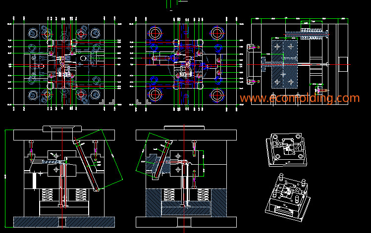
The layout design of a plastic injection mold is a very comprehensive job. To do it, you must understand the gate types, the design and machining of the parting surface, the distribution of the ejector pins and the appearance requirements as well as some common injection defects of the product. The steps of the injection mold layout design are described as below.
Firstly, before you design a injection mold for a particular product, the first thing to consider is the location and type of the gate, which is again affected by the number of cavities and whether the product is an exterior part. There are one-cavity molds, which are usually used for production of large parts or special-shaped products; the two-cavity mold is the easiest to handle, and this layout is the most suitable for the large edge gate or submarine gate, followed by the four-cavity mold, which is the combination of two two-cavity molds, but the length of the runner should be taken into consideration. An appropriate length not only helps save material, but also facilitate smooth plastic feeding; the six- / eight- and sixteen-cavity molds can be said to be the variations of the four-cavity mold. When designing the runner, the upper level runner needs to be 25% larger than the next level runner. In addition, if the product is an exterior part, it is not possible to use the large edge gate for most of the time, because the appearance will be affected. At this point, it is more common to use pinpoint gate and submarine gate located in the ejector pin, but for the latter, the surface of the product might be scratched, so special attention is required.
Second, with regard to the design of the parting surface, the first thing to do is to check the undercut issue. When designing the parting surface, we must also consider the structure, the strength and feasibility of the structure, as well as the machine ability of the parting surface and the processing capacity of the factory. Try to choose a flat parting surface over a curvy one.
Third, if all of the above are confirmed, you can determine the size of the mold core. At this time, all the product drawings should be completed in 1:1. Then copy and mirror and multiply by the shrinkage rate of the product. Next, we use the mirrored and multiplied graph to design the layout. We take the two-cavity mold as an example to explain it – for a two-cavity mold, there is a runner between the two products. Then, how do we determine the length of the runner? Usually, the sprue is at the center of the mold base, so the distance between the two products must be at least able to accommodate the sprue, while guaranteeing the steel strength for the melt to reach the cavity.
If the sprue diameter is 12mm, there must be at least 30mm between the two products. Of course, this also depends on the size and height of the product. It is best to ensure that the center distance between the two products is an integer. Once the centers of the two products are confirmed, the size of the mold core / insert can be determined. Usually, 30mm from the product edge is enough, and some details might need to be adjusted according to the actual situation. The size of the mold core / cavity is mainly affected by the cooling channel and the screws that lock the core / insert. The cooling channel is mainly affected by the size of the product and the distribution of the ejector pin, while the distribution of the ejector pin is based on the product. After all these are confirmed, it is time to identify the size of the mold base, which is prox. the size of the mold core / cavity plus 50mm. But it is still necessary to call the mold base out to check it. A principle must be followed that at least 10mm should be maintained between the edge of the mold core / cavity and the edge of the return pin, while the best distance to the edge of the ejector plate is ±5mm.
Fourth, once the dimensions are determined, what come next are the details, e.g., improving the mold base, and designing mold venting.
Please feel freely to contact us if you are looking for a professional plastic injection molding manufacturer.
Hello, Sir
Thanks for your blog. It’s so amazing. It helps me a lot with the mold layout.
I am currently a CAE engineer and I often simulate the injection molding process by using CAE software. Unluckily, I didn’t have a chance to work with the real injection molding machine in real-life
I have a question about the distance between two products/ cavities/ part. I read your blog about that and understood it. But could you let me know some details about that cavity distance? Is it depend on any parameters or any formulas? Or is it just simply depends on the size and height of the product? Could you tell me how we can determine the minimum distance spacing for any projects depends on size or height (because I am lack of experience in the mold design in real-life)
I would appreciate your feedback.
Best regard,
Khang Tran