Basic Principles of the Slider
Due to the special requirements of a product, the mold release direction of a particular part may not be consistent with the mold opening direction of the injection molding machine (product undercut), the slider,also known as slide,is a mold mechanism that is developed to solve the issues with the undercut. The basic principle is to turn the vertical movement of mold opening / closing into a horizontal motion. In order to cope with the situation that the undercut is located in the core or cavity, different structural forms are developed:
Note:
To mold a product with a deep cavity, of which the side wall does not allow a draft angle, but requires a high gloss, the mold structure also needs to adopt slider mechanism.
Structural Composition of the Slide
The slide mechanism is usually comprised of the following basic components.
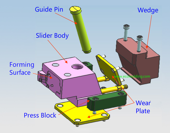
Note:
During slide operation, since the slide, the press plate, the wedge, the guide pin and the wear plate are subject to long-period wear, surface nitriding must be performed to minimize surface wear.
Design of the Angle Pin(Guide pin)
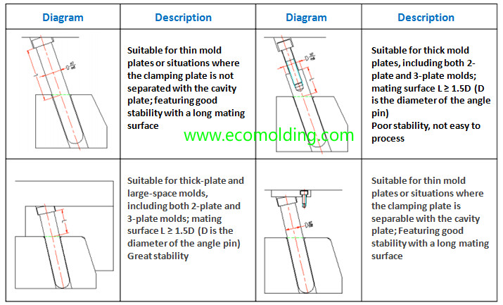
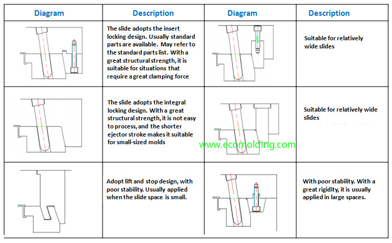
1: How the angle pin locks and where it is used
2: How the Guide Block Moves and Its Design Points
The mold opening action of the injection molding machine is leveraged to make the guide block and the slide move relatively, and surface B engages with the slide to make it move in two directions – the mold opening direction and the horizontal direction, so that it disengages with the undercut. The guide block acts as an angle pin when the mold opens, and as a locking block during mold closing.
See the figure as below:
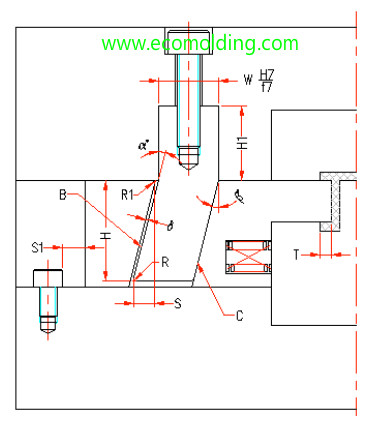
β = α ≦ 25° (α is the tilt angle of the guide block);
H1 ≧ 1.5W (H1 is the corresponding length);
S = T + 2-3mm (S is the horizontal travel distance of the slide; T is the undercut of the finished product);
S = H * sinα-δ / cosα(δ is the gap between the angle pin and the slide, generally is 0.5MM;
H is the vertical distance of the guide block in the slide);
C is the stop surface, so generally a stop block is not needed when the guide block is used (gaps not allowed).
How the Slider Locks
Since great pressure is generated during the plastic injection molding process of a product, to prevent the slider from being displaced by the pressure, which may affect the dimensions and appearance of the finished product (such as flashing), the slider should be locked.
Commonly seen locking methods are shown below:
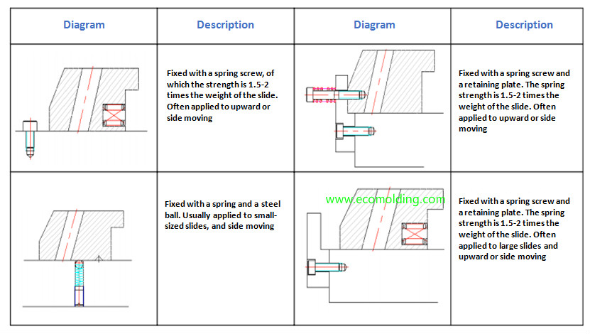
How the Slider Is Located
The slide travels a certain distance during mold opening. Therefore, to guarantee safe slider return, the slider must be equipped with a locking device, which needs to be flexible and reliable to ensure that the slide stays where it is. However, in some special cases, a locking device is not necessary, such as the slider that moves from left to right. But to ensure safety, it is better to have a locking device installed.
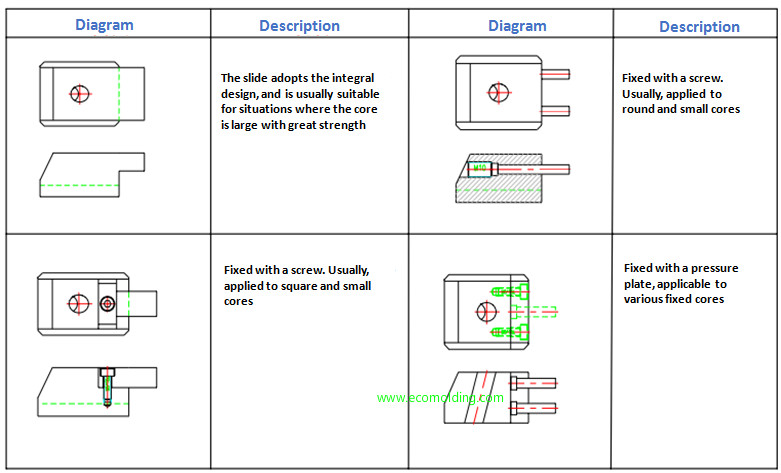
How to Connect the Slider Insert
The connection method for the slider insert is determined by the finished product, since it may vary with different products. The specific connection methods are shown as follows:
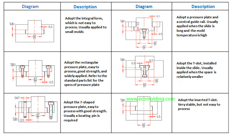
Sliding Guide of the Slide
Sliding guide(sliding rail) has to ensure that the slider moves smoothly and stably, so the slide does not get stuck or bounce during the plastic injection molding process, or product and mold service life will be affected. Sliding guide has to ensure that the slider moves smoothly and stably, so the slider does not get stuck or bounce during the plastic injection molding process, or product and mold service life will be affected.
The commonly used sliding guides are shown below: