Common Structures and Types of the Lifters
As shown in the following figure:
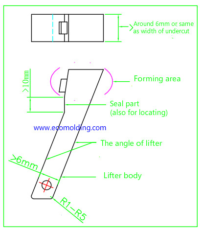
Generally speaking, a lifter generally consists of two parts: the body and the forming parts.
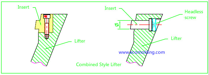
Similar to the slide, the lifter can be classified into: the integral lifter and the non-integral lifter (combined Lifter), according to whether the body and the forming parts are integrated. Please note that since the lifter is relatively small in size, we usually opt for the integral lifter but rarely choose the combined one. The integral lifter is compact, strong and resistant to damage. For larger lifters, the design can adopt the combined form, making replacement convenient, while also easy to maintain and repair, with relatively simple processing.
Besides, according to the different locating structures at the lower end of the body, the lifter can be further classified into: the cylindrical lifter and the T shape lifter. With regard to these two lifters, the cylindrical lifter is widely applied in mold design, for which the main reason is that it is easier to process, install and maintain, while the T shape lifter is mainly used for larger products that have higher requirements for precision. Since it also needs to be matched with a special T-shaped base , it is more difficult to process while also increasing the manufacturing cost.
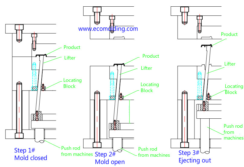
How the lifter moves
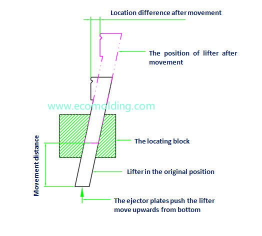
As shown in the figure on the left, the lifter is placed in an angled hole in a locating block, with the appropriately fitting in the angled hole.
Give the lifter a push from the bottom up, which moves it up for a certain distance. Now we find that the lifters not only moves upwards under the forcing of the angled hole and the push, but also moves a certain distance in the direction that the lifter inclines (see the location differences shown in the figure). During the ejection process, since the product is in a vertical motion, but the lifter not only moves vertically, but also moves in the opposite direction of the undercut, so that the undercut can be more easily release
Lifter Design
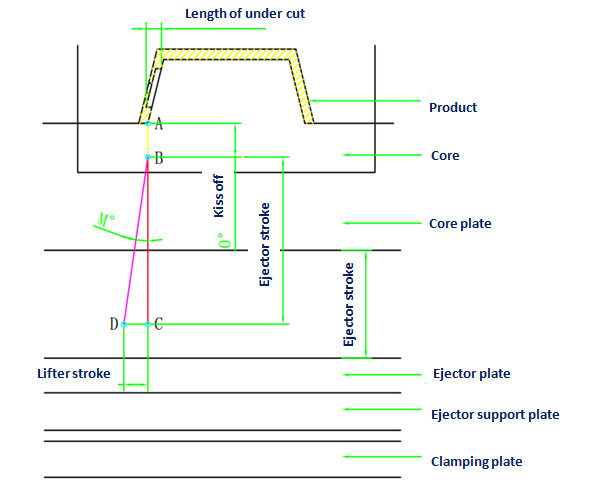
1. Prerequisites: The dimensions of the mold plate, core, and base have been determined. The specifics are as shown in the following figure. Now, read the drawings and analyze them carefully to determine the size of the dead corner, as shown in the figure.
2. Determine the starting point of the 0° kiss-off surface and its length (as shown in Figure AB). If you do not design a 0° kiss off, make point A the starting point for the lifter slope.
3. On basis of point B, the offset distance as shown in Figure BC = ejector stroke.
4. On basis of point C, allow a certain offset distance in the opposite direction of the lifter movement, as shown in Figure CD. CD = lifter stroke (get a rounded number) = undercut length + min. safety amount that’s greater than or equal to 3mm.
5. Link up D and B to get the angle DBC. This angle is usually a decimal. Let’s take a rounded figure M°. So, this is the tilt angle of the lifter slope, which we need.
6. With regard to other contents, the design of other lifter components can be completed according to the structure and requirements described above.
As a matter of fact, the main purpose of the content as complicated as the above is intended to show us how to find the tilt angle of the lifter. We are able to simplify it as shown in the following diagram:
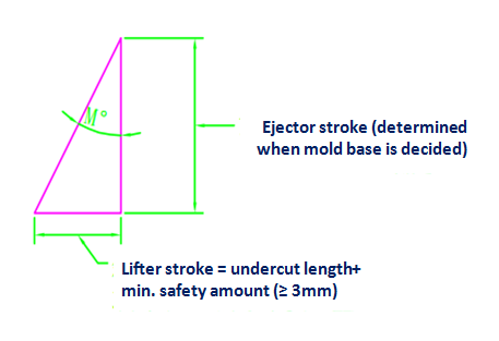
As the above figure indicates, we can get the trigonometric function tgM° = lifter stroke / ejector stroke. It is very easy to figure out how big M° is at the moment, or it can be measured directly on the drawing.
Please feel free to contact us if you are looking for a professional plastic mold making company.