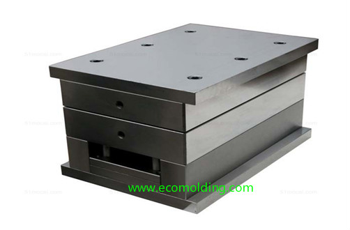
As the framework of a complete set of molds, the mold base is the main part of a mold. It is assembled from a diversity of steel plates and parts. It is a very important step in mold production to select an appropriate mold base, because the size of the selected mold bases directly influences the quality of the mold. If the mold base is not appropriately selected, not only will it lead to mold development failure, but also the mold base will be scrapped.
So, what are the mold bases selection principles? What are the application conditions of the side gate mold bases, point gate mold bases and simplified point gate mold bases? What are the calculation methods for the selection of mold bases?
Mold Bases Selection Principles
When selecting a mold base, multifaceted aspects, e.g., part structure, mold parting requirements and economy should all be taken into consideration. The mold base selection principles are shown as follows.
Side Gate Mold Base
Conditions for Selection
1. Simple structure, not-very-strict requirements for surface finish, allowing gate marks on the side, and no other special structures.
2. When the side gate mold bases are applicable, don’t select the pinpoint gate mold base. The side gate mold base is applicable to the one-step parting mold.
Point Gate Mold Base
Conditions for Selection
1. When the single-cavity and the molded part have a large projection area on the parting surface, requiring multipoint feeding, the pinpoint gate mold bases are usually selected.
2. For a multi-cavity mold, in which some individual parts require feeding from the inside.
3. For a multi-cavity mold, the sizes of some individual cavities vary a lot. When using edge gate, the gate bushing should be away from the center of the mold.
4. Gear mold, and multi-cavity tire mold, etc.
5. High barrel, or shell shaped products.
6. For molds of high precision products, or those with smaller dimensional tolerances and higher requirements on service life, select the pinpoint gate mold base.
Simplified point Gate Mold Bases
Conditions for Selection
1. When there are large-size core-pulling mechanisms (slides, cylinders) on both sides, it will take a long time if the pinpoint gate mold base is selected. In this case, the simplified pinpoint gate mold base is a better option.
2. The side gate mold with a cavity slide usually adopts the GAI and GCI series of the simplified pinpoint gate mold base.
Tips
1. When the overall size of the mold base is below 250mm (including 250 mm), the I-shaped mold base is used. When the mold base size ranges between 250 and 350mm, the T-shaped mold base is used. For the mold base larger than 400mm, selected the T-shaped mold base when there is a slide, and use the H-shaped mold base when there is no slide.
2. When the frame of Plate A is deep (usually greater than 60mm), consider the application of the through-frame or the H-shaped mold base; for the mold bases with a slide or a cavity slide, Plate A should not adopt the through-frame. When Plate A frame is deep (usually greater than 60mm), consider using a H-shaped mold base.
3. The mold base with an ejector plate must not be paired with cavity guide pin and guide bushing in core.
4. When the mold core is circular, use the mold base with a support plate.
5. When there is a slider or a cavity slider, the guide pin needs to extend 10-15mm before it can be inserted into the slider, i.e., when the guide pin is particularly long, cavity guide pin and core guide bushing are used, so as to lengthen the guide pin.
The Calculation Method for Mold Base Selection
The form of the mold base is determined first, followed by the size, which depends mainly on the size of the mold core. The larger the size of the mold core, the larger the size of the mold bases are. The relationship between the two is proportional.
1. Determine the Width of the Mold Bases
The width of the mold bases ejector pin should be the same as the width of the mold core. The difference between the two should be kept within 5-10 mm.
2. Determine the Length of the Mold Bases
The distance between the length side of the mold core to the outer edge of the return pin should be greater than 10-15mm, and the mold bases of over 40mm should adopt a length of 15mm.
3. Determine the Height of the Mold Bases
The height of a mold base mainly refers to the height of Plate A, Plate B and the spacer plate. The thicknesses between other plates are all standard. So, adjustment is not required when selecting or calculating the mold base.
(1) Height of A Plate: for T-shaped mold bases, the height usually equals the depth of A Plate frame, i.e., 20-30mm; : for H-shaped mold base, usually Height = Frame Depth + 30-40mm.
(2) Height of B Plate usually = Depth of B Plate Frame + 30-40mm; if a through-frame is to be opened on the mold core, a support plate is needed, of which the height has already been standardized.
(3) Height of C Plate : The height of the spacer plate needs to be calculated after determining the ejector stroke of the product. Smooth product ejection must be ensured. Generally speaking, it equals product ejector stroke + the preset clearance of 10-15mm. It is not allowed to eject the product after the ejector plate touches the support plate. Therefore, when a product is high, a spacer plate should be added.
Tips :
1. When an ejector guide pin is used, the guide pin in the copper guide bushing must be accordingly equipped. The diameter of the ejector guide pin is usually of the same size with the return pin of a standard mold base, but it also depends on the length of the guide pin. It is appropriate for it to extend 10mm into the support plate or B Plate .
2. A Plate (B Plate) must be equipped with four 25.4mm x 450mm pry slots , of which the depth is usually 5mm.